35. LM3914 VU meter
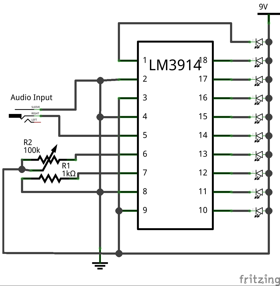
In the next project, This unit will demonstrate the audio levels visually, through 10 levels of LEDs in the form of VU, which stands for Volume Units. To display the levels, an lm3914 chip is used for the project, along with the lm386 module, to act as a backup amplifier.
 |
| <Full unit> |
Once everything is implanted, the lm3914 circuit indicates the number of decibels (or signal levels) coming from the sound source and outputs it to show the user the level of audio coming out from it. In this case, the louder the audio source, the more LEDs that light up, and the quieter the audio source is, the fewer LEDs it lights up-sometimes the LEDs don't light up at all when the decibel level was at 0.
 |
| <Front view> |
The LEDs were placed together in a "matrix" form, yet it forms a 1/8 note at the very end. Each of the LEDs was wired up in parallel for each layer so that the chip can light each Led for a VU look. Once the matrix is done, it's wired up to the Lm3914, along with a few discrete components to finish it up. As this project is finished, the lm386 is implanted next, since as mentioned, it will function as a backup amplifier, as well as a signal boost for the VU meter circuit.
 |
| <Side view> |
Once the wiring was done, it was then housed in 2 wooden boards, where one of the boards has holes being dilled out until it once again, makes the 1/8 note on the board (shown in the pictures). The LEDs will then fit these holes, making a snug fit once they are inserted inside. The bottom board will be the base, where it will support the entire circuitry upwards, without collapsing.
 |
| <Back view, w/ internals> |
It's a fun project, giving you skills in learning an IC component, as well as seeing the levels of decibels through leads. It may also function when you want to run a party that utilizes VU meters, and so on.
VU Test
 |
| <Circuit> |


Comments