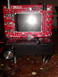
41/KIT. TFT Oscilloscope w/ signal generator
This project is an essential tool used by an average electrical/electronic engineer. Like the bench power supply and other various electrical equipment, it is mainly used for assisting the person when it comes to creating circuits.
 |
| <Entire unit> |
The kit is named the DSO138 oscilloscope, which provides most of the functions of a regular oscilloscope. The key function of any oscilloscope is that it can detect electrical signals, and displays these signals to the screen as waveforms. Amplitude, frequency, rise time, distortions, intervals, and so on, were the properties of the displayed waveforms and can be analyzed further for detecting the signal.
 |
| <Oscilloscope> |
Since it costs $20, there are certain limitations over what the more expensive oscilloscope can do. This includes: controlling the device with buttons instead of knobs, limited screen size, the limit creating waveforms at the maximum frequency, and many more.
However, as mentioned from the beginning, it can perform what the regular oscilloscope can do in most cases. This kit is suited for preparation, which in this case, is a training device before you purchase an expensive oscilloscope. Otherwise, the oscilloscope kit can be used for any basic functions, such as detecting waveforms from electric signals, detecting PWM signals, and so on.
 |
| <555 signal generator> |
To make sure the oscilloscope is working, you will need a signal generator that can create different waveforms, as well as adjust the amplitude. The particular generator uses a 555 chip, which has a variety of timed-based applications, especially oscillator applications.
There, the output uses a series of resistors and capacitors to create different voltage levels-allowing the circuit to create different waveforms. The potentiometer adjusts the amplitude, making it easier to distinguish different waveforms without scrolling down/up with the oscilloscope. The switches will help the user change the waveforms.
The circuit is housed in a plastic box with bolts, and then the oscillator was then mounted on top of the enclosure to make it stand up. Certain holes have to be drilled for wire access, switch, LED, and so on.
<Test with signal generator>


Comments