52. Pi-Laptop V1
This project will use the Raspberry PI, which we will now turn into a full-fledged portable laptop. In Project 47, The PI was set up as a desktop computer, where you can perform basic tasks-similar to what you can do with an average desktop PC at the time. The difficulty to set it up was small, from connecting the board with other devices to installing the OS, but when it comes to making it portable, a few extra steps were needed to make it functional.
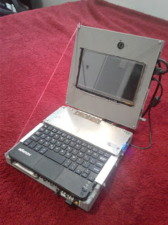 |
| <Entire device> |
The OS installation was exactly the same, but with new parts, it can get challenging. To start with for the laptop, you will need housing to hold the components in, which can be solved by creating a model on Autodesk, importing it on STL to Gcode format, and then 3d printing it with a PLA filament. Any printer should work, like the Anet A8 printer, and to make the housing stronger, make the infill about 60% or higher.
 |
| <Starting assembly> |
You will also need a 7" LCD screen, which needs to have an HDMI input so you can plug the HDMI cable from the PI into the display. it can be mounded in the second piece of the housing, which acts as the lid of the laptop. Make sure that the display is secured, so that it will not shake in motion, but also make sure that the screen orientation is correct. The batteries were Li-ion cells-all connected in parallel to increase the capacity, and the laptop runs longer. Both the battery pack and the PI were mounted to the first housing, which serves as the body of the laptop. double-sided tape and screws were used to secure them on the housing. Other devices, such as the USB hard drive, and the USB hub, can be mounted there as well. Just make sure that there is room to make all the wiring. To get sound from the PI, you need to locate the pads PP25 and PP26 underneath the PI board, and solder the wires, with the ground connection.
 |
| <Power supply> |
Once the wires were soldered in, connect the wires to the audio input of an amplifier board, which in this case, the PAM8403. Then solder the speakers to the PAM8403 output. to get 5 volts from the Li-ion batteries, you will need to get dc-dc boost converters, which were set up to 5 volts for each. To increase the Amperage from the boosters, connect them both in parallel, output to output and input to input-just make sure they are at the exact voltage set. 3 boosters were used, 2 for the PI, and the last for the display. To charge the battery pack, you will need a tp4056 module, but this time, it should have 3 tp4056s in the board, so that it can deliver up to 3 amps-just enough to charge the pack than 1 amp. To see the battery voltage from the pack, I used a small led segmented voltmeter, which gives out a proper level of voltage (4.2V-full and 2.8-empty)
 |
| <Near completion> |
Once everything was put into place, the wiring starts, with the battery pack connected to the main switch, and then on the other side of the switch, it connects to the dc booster. The charging module connects directly to the pack, and the dc converters will each connect to the screen and the PI board separately to power them up. The voltmeter connects to the other connection of the switch, and so is the pam8403 amplifier. Make sure that the connections are secure, and that there are no shorts when powering the laptop. The setup for the OS is the same as before, just copy the files of the NOOBS to the sd card, transfer them to the PI, and then hook it up to the external display to further install it. Once it was done, disconnect the E.display so you can connect it to the 7" display. Attach the 2 housings with hinges, and use a string to set it in place, apply for the cover plates, and you are done!
You will be able to use it like any laptop, but with the GPIO pins, you will experiment with Python, and so on.
<TEST>


Comments