6. RF free energy
< Intro >
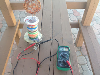
This project was interesting to me, as the concept of harvesting energy from the thin air seems impossible, but it does work, and here is such a device that can do so - powering things such as an LED. Instead of collecting energy through conventional means like solar, wind, hydro, or any other, this one uses RF(or electromagnetic) waves in the air, which are then collected by the antenna, and into the circuit where it gets converted into small but usable electricity. While it does work, it shouldn't be your main source of energy, because of course it cannot power devices that use more watts such as a computer, I just built it for fun, and also to see how it works!
 |
| <Entire RF device> |
<How it works>
Since the device works similarly to a crystal radio, it relies on its long antenna to collect all the RF waves right into the antenna, and the longer the antenna, the more it can collect for more power. Keep in mind that even if we got that energy using the antenna, the energy density is very low, and it needs to be rectified to ensure the output is all direct current because the current flowing through the antenna is also AC in nature. Once the current from the antenna now flows into the circuit, it then goes to the 2 main capacitors for coupling as well as isolating any dc current that may pass through the diodes, and speaking of the diodes, they rectify the ac current into dc current before they pass to another set of capacitors. Those last 2 capacitors smooth out the DC current and also act like batteries, storing the energy for later use.
Build-wise, the circuit is pretty easy to create, only the setup such as the antenna placement is what makes the results vary in terms of its output. The capacitors on the antenna side can be any non-polarized type, but the diodes need to be the germanium type (such as the 1n34), as those have a very low voltage drop, and so they can rectify the current without any further power loss.
 |
| <Closeup> |
While testing out this circuit, I wonder if I can improve it further, so what I have done is make a grounding connection by reusing parts of the antenna (taking one of the wires off), and connecting it to where the ground should be (on the metal body), just like all other crystal radios. The purpose as to why the ground is necessary for improvement is because it gives the electrons from the circuit a way to exit out, basically forming a complete circuit, almost treating the entire RF waves and air as a "battery".
In short, my setup consists of an antenna high up in altitude, and the ground
Also, the 2 antennas were no longer, the first one was connected to a random metal bar, and the other one was a copper coil stretched, and placed next to the bar. This, in turn, gives the device more coverage in collecting the RF waves more easily, while maintaining a steady current flow similar to an old crystal radio.
Here's what I discovered in each experiment:
August 28:
>E1: started with a secondary coil for the antenna, no ground.
>Results: it achieved a voltage of over 2.0 volts as a start, where it only powers just 1 LED.
August 29- September 2:
>E2: Attached 3 antennas for better coverage, removed the secondary coil,
and used the entire hand and body for the ground, with the help of the Altoids tin as a new metal enclosure for the circuit.
>Results: it achieved a voltage of over 4.0 volts, enough to power 4 LEDs in parallel instead of just 1 LED, and still enough to power a calculator.
September 3 (shown in the pictures below):
>E3: removed 1 antenna in order to convert that wire as a ground wire and made the 2 antennas longer for better coverage.
>Results: By a glance, it reached a voltage of 9-10 volts before decreasing, which is enough to power 8 LEDs in parallel, with a slight increase in brightness!
> Notes: In the photo on the left, the left wire is the ground, and the 2 right wires are the antenna.
Calculator test
 |
| <RF Circuit> |


Comments