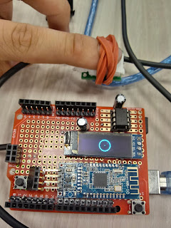
65. Arduino heartbeat detector.
For this project, we are going to experiment with the Arduino by making it detect heartbeats using the infrared emitter and detector. These 2 components will make heartbeat detection possible while remaining cheap. The way the setup works is that the IR emitter sends out a continuous wave of infrared to the human tissue (Such as on a finger), which contained the necessary blood flow. Once the IR light hits the blood circulating area, it then reflects back to the IR receiver, which can take the data, and sends it to the Arduino for serial display.
Due to the blood flow fluctuating the amount of IR, the value changes every time there was a heartbeat. Of course, because it's analog, the data/signal can get messy, but there is a way to make it less messy, and more accurate.
 |
| <Breadboard test> |
To start with the build, you need the IR pairs, as well as an LM386 opamp, and discrete components, to limit the current and pull down the signal. it's important to have the IR emitter and detector close to each other so that when a user's finger is being used on top of the IR pair, it will be easy to get the data for the Arduino.
With the basic setup in place (Without the op-amp), connect the wire from the capacitor to pin A1 of the Arduino. This is where we get the analog data since it will show more data than just 0s and 1s of the digital pins.
To see if the IR emitter was working, try to get your smartphone, and put it into the camera app. if you can see a purple spot on the emitter, then you know that you wired the emitter correctly, if not, try again.
 |
| <Breadboard test 2> |
With the basic setup done, try to work on the same setup, but with the LM386 as well. The main purpose of the LM386 is to boost the input signal by a higher gain, and so once it's implanted, the incoming signal from the IR receiver will be greater. The LM386 also requires its own external power like the IR emitter and detector, so make sure that the chip is powered up properly.
Once you get the edited setup connected, hook the wire from pin five of the LM386 to the same Analog pin from the Arduino. At this point, you will see a greater change in the signal, being that the amplitude was noticeably higher.
There is still some noise on the output signal, what we can do to edit the signal was to add a low pass filter function on the code and add a derivative equation for the code.
 |
| <Under testing> |
The purpose of the low pass filter was to let the low frequencies through while cutting off the high frequencies. This makes it useful when you are trying to get the low-frequency data, and so you want the high-frequency data removed.
The purpose of the derivative in a sense for this project was to edit the signal so that it goes in a more slope appearing. In other words, rather than having fluctuating data, the derivative makes the estimate of what the data path is going for, and so smooths it out to make it cleaner.
At this point, you are ready to see your heartbeats on a serial monitor, or even with the OLED display!


Comments