55/KIT. Escape robot
For this project, we'll be taking a look at one of Elenco's products, the Escape robot kit. The robot has the function of escaping its way out.
 |
| <Entire robot> |
The way this robot work is that it has 3 IR emitters and 1 IR receiver. It also utilizes a microcontroller to serve as a brain-controlling the motors, generating the signal for the IR emitters and responding on which the IR beam is detected. since it has 3 IR beams, if one of the beams was detected, the receiver will take that information to the microcontroller, and the microcontroller will make the motors turn in the position that was in from one of the three IR beams.
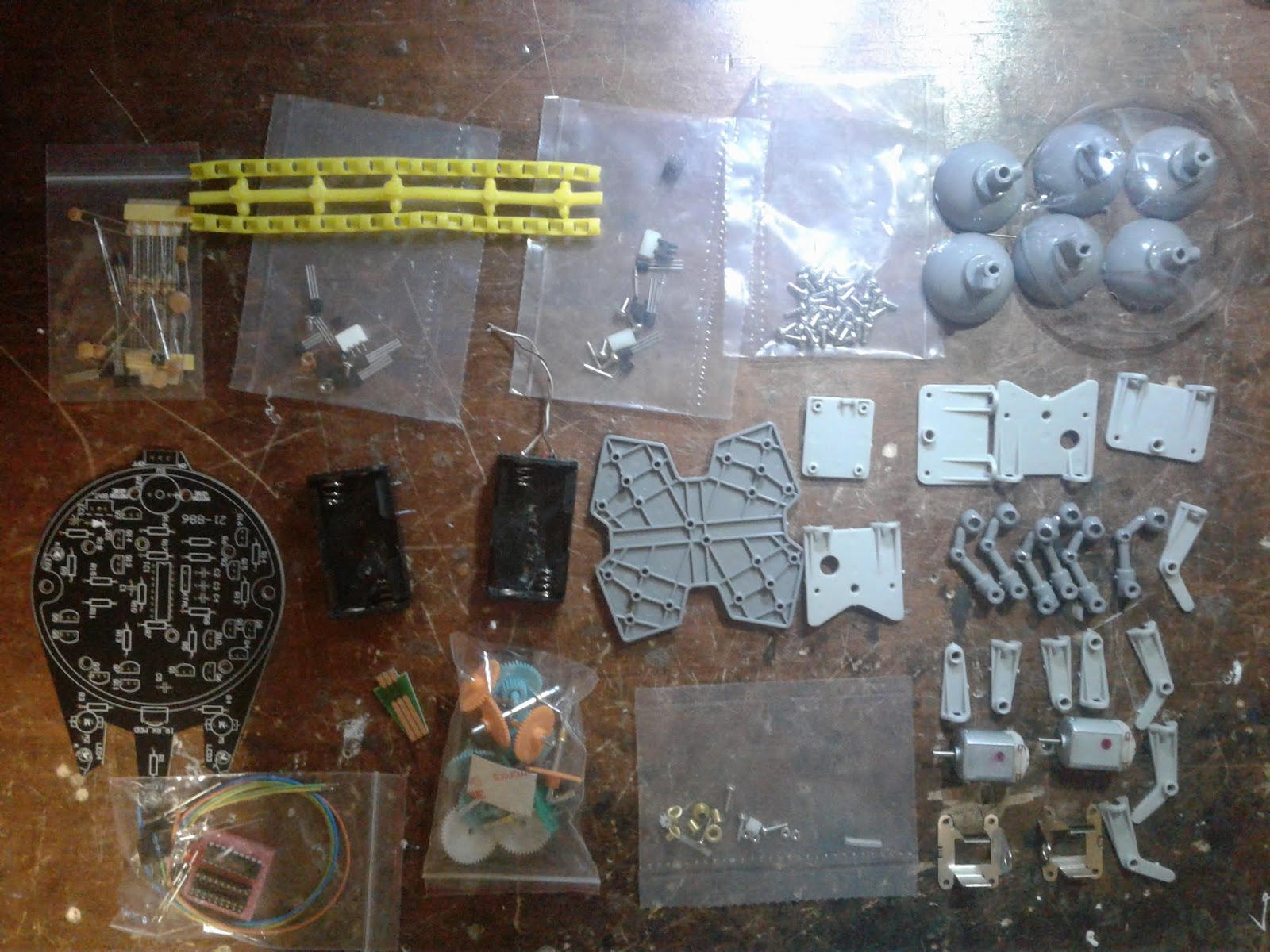 |
| <Parts in the kit> |
The kit itself requires the mechanical build and the soldering job. The mechanical build is for assembling the chassis, which houses all the gears needed to convert the speed of the dc motor into torque.
The soldering part is for assembling the entire circuitry for the robot, which includes the pre-programmed microcontroller, but also a bunch of discrete components such as resistors, capacitors, transistors, and motors.
 |
| <Chassis> |
To start with the assembly of the chassis/gearbox, you will need to get the base first, as this is where the entirety starts. Refer to the instructions on how to assemble the chassis, since the plastic pieces can get a little confusing as you assemble.
Once you got the plastic pieces, insert the 2 motors, and you can move one to assemble the gearbox. Again, refer to the instruction manual, which shows you which gear to put in which shaft. Test frequently to make sure the gears spin in the right direction.
its always a good idea to hook up one of the 2 motors to a power source, and see if the gearbox is spinning all 3 shafts. If it works, you can install the provided wheels for each of the shafts.
 |
| <Circuitry> |
The second part of assembling this robot is to solder the components to the PCB board. Refer to the instructions again to make sure that the components are soldered to the right area, especially with the polarity of certain components such as the IR emitters, and the led.
Once all the components are soldered in place, you can fuse them together by connecting the wires of the motors to the right pins from the PCB, screw the PCB to the chassis with screws, install new batteries, add a cover, and you're done.
Comments