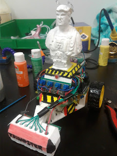
59: Line following robot
This project will be consisting of an Arduino board, which will be used as the brains of the robot, as well as the motor shield to drive the motor, a couple of potentiometers, and resistors/photoresistors. The Arduino board has to be the Arduino Mega, which is the same as the Arduino UNO, but it has more digital pins to use and features a better microcontroller.
The way this robot work is that it senses the black line over the white area using 7 photoresistors. The photoresistors are set up with the resistors in a voltage divider configuration. The resistor is connected to the positive, the photoresistor is connected to the ground, and the last ends of the photoresistor and resistor are connected together as a signal out.
 |
| <Starting parts> |
That way, when the photoresistor senses the line, the voltage changes, and so the Arduino will use that information, sends the signal to the motor shield, and then drives the motor.
To make sure the Arduino responds according to the data from the photoresistors perfectly, it's programmed by a PID configuration.
PID, also known as proportional, integral, and differential, is basically controlled loop feedback that allows controlling the loop easier.
For setting up the PID as well as the speed, the potentiometer was used to control each part to enhance the PID and speed if things went out of the loop or don't follow the line well.
 |
| <Chassis> |
The robot needs to have housing of some sort, which in this case, there are 3 parts for a full robot chassis.
The body has to be 3d printed, so that the electronics and the motors can fit inside without moving all around, and provides great integrity support.
The battery holder must hold the 9-volt battery supply so that it also doesn't move around. Lastly, the sweeper(front part) has to be glued to the front of the body, so the photoresistor array will be mounted in the sweeper part.
 |
| <First build> |
It's only a matter of time before wiring the photoresistor outputs to the analog pins of the Arduino board, and wiring the photometers to the first digital pins of the Arduino. Then, make sure that the motor shield is connected firmly on top of the Arduino board, as well as make sure the motors are connected to the shield. Program the Arduino board with the line following code, connect the battery to the board, and test it with a black line on a blank paper.
That process is simplified, and it requires some fine-tuning, but it's rewarding to see the robot finally following the line when did the steps and calibration correctly!


Comments